How to Test Continuity with a Multimeter
June 9th , 2026 | AstroAI *
How-To Guide • Multimeters • Electrical Fundamentals

How to Test Continuity with a Multimeter — A Practical Step-by-Step Guide
Written by: AstroAI Editorial Team
Technically reviewed by: AstroAI Product Engineering Team
Last updated: June 9, 2026
You plugged in a lamp and nothing happened. The fuse looks fine. The outlet works. So is it the switch, the cord, or a break somewhere in the wire? A continuity test gives you a definitive yes-or-no answer in about 30 seconds — no guesswork, no disassembly beyond what you'd do anyway to replace the part. Every multimeter with a continuity setting can do this, and the test itself is the same whether you're checking a car fuse, a wall switch, a section of wire, or an extension cord. This guide walks through exactly how to set up the meter, what to do with the probes, and how to read the result — for each of the most common use cases.
Quick Answer — How to Test Continuity with a Multimeter
A continuity test checks whether electricity has a complete path to flow through a fuse, switch, wire, cord, or other component.
- Turn off and unplug whatever you are testing. Continuity tests only work on de-energized components.
- Plug probes in: black lead → COM jack, red lead → VΩ jack.
- Set the dial to the continuity symbol (looks like a sound wave: )))) or the diode symbol if your meter combines them. On meters without a dedicated continuity mode, use the lowest Ω range.
- Self-test: touch the two probe tips together — you should hear a beep and see a reading near 0 Ω.
- Touch one probe to each end of the component. Beep + near-zero resistance = closed path / continuity. Silence + OL or “1” = open path / no continuity.
Key rule: Always test with the power off. Applying live voltage to a meter in continuity mode can damage the meter and is a shock hazard.
1. What Continuity Actually Means — and Why It Matters
Continuity means there is a complete, low-resistance path through which current can flow between two points. When a component has continuity, electricity can pass through it unimpeded. When it does not — because a wire is broken, a fuse has blown, or a switch contact has burned out — that path is interrupted and the component is effectively dead.
The continuity test is one of the most useful functions on a multimeter precisely because it is binary: the answer is either "current can flow" or "it cannot." In continuity mode, a digital multimeter sends a small test current through the component and triggers an audible beep when it detects a complete path — the beep lets you focus on probing the component rather than watching the display.
The test applies to anything that should conduct electricity from one end to the other: fuses, switches, wires, extension cords, circuit board traces, heating elements, motor windings, and more. It does not measure how much current a component can carry — only whether the path exists. For anything that should block current (an open switch, a blown fuse), you expect no continuity. For anything that should conduct (a good fuse, a closed switch, an intact wire), you expect continuity and a beep.
2. What You Need and How to Set Up the Meter
2.1 Equipment
- A digital multimeter with a continuity mode or Ω (resistance) mode — virtually all modern meters qualify
- The supplied test leads in good condition (check the insulation for cracks before each use)
- The component you want to test, removed from any live circuit
2.2 Meter Setup
- Insert the black test lead into the COM jack and the red test lead into the VΩ jack.
- Turn the selector dial to the continuity symbol — it looks like a small sound wave ()))). On many meters, this position is shared with the diode test; press the function button to switch between them if needed.
- If your meter has no dedicated continuity mode (older analog meters), set it to the lowest Ω range — typically 200Ω. You will read resistance instead of hearing a beep, but the logic is the same: near-zero = continuity, OL or infinite = open circuit.
- Self-test the meter: touch the two probe tips together. A working meter will beep and display a resistance value between 0 and 2 Ω (accounting for the leads' own resistance). If nothing happens, check the battery.
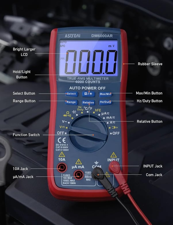
Use the dial markings and input jacks as a visual reference when setting continuity mode.
2.3 Safety Before You Start
- Always de-energize the circuit before testing. Applying live AC or DC voltage to a meter in continuity mode will at minimum damage the meter's internal circuitry, and at worst blow the meter's fuse or create a shock hazard.
- For wall switches and outlets: turn off the breaker for that circuit and use a non-contact voltage tester to confirm the wires are dead before disconnecting anything.
- For car fuses and automotive components: disconnect the battery negative terminal if you are working near the fuse box, or simply pull the fuse free before testing.
- Discharge any capacitors before probing circuit boards — a charged capacitor can send a spike through the meter and damage it.
2.4 When NOT to Use Continuity Mode
Continuity mode is not a live-circuit test. Do not use it on energized outlets, breaker panels, active vehicle circuits, EV or hybrid high-voltage systems, or circuit boards with charged capacitors. If your goal is to confirm whether voltage is present, use voltage mode or a non-contact voltage tester first. Continuity mode should only be used after the component has been powered off, unplugged, removed, or otherwise isolated from live voltage.
Continuity Test Result Cheat Sheet
| Meter result | Meaning | Common cause | What to do |
|---|---|---|---|
| Beep + 0–2 Ω | Strong continuity | Good fuse, closed switch, intact wire | Component likely passes |
| Beep + higher resistance | Continuity with resistance | Long wire, coil, corroded contact | Check expected spec |
| No beep + OL / 1 | Open circuit | Blown fuse, broken wire, open switch | Replace or repair |
| Intermittent beep | Unstable path | Loose terminal, damaged wire, corrosion | Wiggle-test and inspect |
Use the table above as a quick reference. For fuses, short wires, and closed switches, a beep or very low resistance is usually the expected result. For coils, heating elements, sensors, or long cables, compare the resistance reading with the component's specification.
Continuity Mode vs. Resistance Mode: Which Should You Use?
Use continuity mode when you need a fast pass/fail answer: is this fuse, switch, wire, or cord electrically connected from one end to the other? Use resistance mode when the actual ohm value matters, such as checking a motor winding, sensor, heating element, or long cable. Continuity mode is faster because the beep lets you keep your eyes on the probes, but resistance mode gives a more precise number.
| Use case | Best mode | Why |
|---|---|---|
| Fuse | Continuity | Pass/fail check |
| Wall switch | Continuity | ON should beep, OFF should not |
| Extension cord | Continuity + short check | Confirms each conductor and no internal short |
| Motor winding | Resistance | Actual ohm value matters |
| Sensor | Resistance | Compare to spec |
How We Verified These Continuity Testing Steps
AstroAI verified the steps in this guide using common household and automotive test cases: a removable blade fuse, a basic wall switch, a two-conductor extension cord, and short sections of insulated wire. The procedure was checked with the meter in continuity mode and confirmed again with resistance mode where applicable. The goal was to make the instructions practical for beginners while keeping the safety rule consistent: continuity testing should only be performed on de-energized and isolated components.
| Test case | What was checked | Expected result |
|---|---|---|
| Blade fuse | Probes placed on both fuse terminals after removal | Good fuse beeps; blown fuse shows OL or no beep |
| Wall switch | Switch terminals checked in ON and OFF positions | ON beeps; OFF shows OL or no beep |
| Extension cord | Matching prong/slot pairs checked, then opposite pairs cross-checked | Matching pairs beep; crossed pairs should not beep |
| Single wire | End-to-end path checked on an isolated wire section | Intact wire beeps; broken wire shows OL or no beep |
3. How to Test a Fuse for Continuity
A fuse is the simplest continuity test you will ever do. A good fuse conducts from one end to the other; a blown fuse is an open circuit. The test works identically for car blade fuses, glass tube fuses, and cylindrical cartridge fuses. You do not need to know the fuse rating — only whether continuity exists.
Steps
- Remove the fuse from the fuse box or holder. For car blade fuses, pull straight out with a fuse puller or needle-nose pliers.
- Set the meter to continuity mode and self-test by touching the probes together.
- Touch one probe to each end (terminal) of the fuse. For a blade fuse, touch the two flat metal tabs at the top.
- Listen and read: a beep and near-zero resistance means the fuse is good. Silence and OL means it has blown — replace it with a fuse of the same amperage rating.
Visual check is not enough. Some fuses blow internally without any visible wire break — especially ceramic fuses and some fast-blow types. A continuity test is the only reliable way to confirm the fuse is working.
4. How to Test a Wall Switch for Continuity
A wall switch that feels fine mechanically can still have burned or oxidized contacts that prevent current from flowing when it is in the on position — or, less commonly, fail to break the circuit when it is off. A continuity test checks both conditions in about two minutes.
Steps
- Turn off the circuit breaker for that circuit. Verify the circuit is dead with a non-contact voltage tester or by testing the outlet it controls.
- Remove the switch cover plate and unscrew the switch from the electrical box. Disconnect the two wire leads from the switch terminals (note which color goes where if you are reinstalling it).
- Set the meter to continuity mode.
- Test with the switch ON: flip the switch to the on position and touch one probe to each terminal. You should hear a beep — the closed switch provides continuity.
- Test with the switch OFF: flip to off and repeat. The meter should be silent and show OL — an open switch has no continuity. This is the expected state.
| Switch Position | Expected Result | If Result Is Opposite |
|---|---|---|
| ON | Beep — continuity present | Switch contact is burned out — replace switch |
| OFF | Silence — no continuity (open circuit) | Switch is welded closed — replace immediately, a safety hazard |
5. How to Test a Wire or Extension Cord for Continuity
A wire that looks intact on the outside can have a break inside the insulation from a pinch point, a sharp bend repeated over time, or being run over by a vehicle. An extension cord can have one conductor broken while the other still works — a condition that is dangerous and invisible to the naked eye.
Testing a Single Wire
- Disconnect both ends of the wire from any circuit.
- Touch one probe to each end of the same wire — one probe at the beginning of the conductor, the other at the far end.
- A beep means the wire is intact end-to-end. Silence means it is broken somewhere along its length.
- To find where the break is: divide the wire roughly in half, splice or clip a probe to the midpoint, and test each half. Repeat on the broken half to narrow the location.
Testing an Extension Cord (Two-Conductor)
- Unplug the cord completely from any power source.
- Test the first conductor: touch one probe to a male prong at the plug end and insert or clip the other probe to the corresponding female slot at the receptacle end. For a standard two-prong cord: wide prong → wide slot; narrow prong → narrow slot. Beep = good.
- Test the second conductor by repeating for the other prong/slot pair.
- Cross-check for a short circuit: touch one probe to the wide-prong side and the other to the narrow-slot side (deliberately crossing). You should get no beep. If you do, the two conductors are touching somewhere inside the insulation — the cord is unsafe and should be discarded.
6. Common Mistakes That Give Wrong Results
Most failed or confusing continuity tests come from one of three mistakes — none of which are difficult to avoid once you know to look for them.
Mistake 1
Testing a live circuit
Live voltage overrides the meter's test signal. You may get a false reading (beep when the wire is broken, or a wildly incorrect resistance value). Worse, you risk damaging the meter or shocking yourself. Always confirm the circuit is dead first.
Mistake 2
Not isolating the component
If you test a switch while it is still connected to the circuit wiring, parallel paths through other components will create a false continuity reading. Disconnect the component from the circuit before testing — both ends, not just one.
Mistake 3
Skipping the self-test
If the meter's internal battery is low, the continuity beep may not trigger reliably — you get silence even on a known-good component. Touch the probes together before every test session. No beep = replace the battery before drawing conclusions.
7. Which AstroAI Multimeter Is Right for Continuity Testing?
For continuity testing alone, the most important features are not brand-specific: a clear audible beep, safe input jacks, reliable test leads, a working self-test, and a resistance mode for double-checking readings. Any properly functioning digital multimeter with continuity mode can perform the basic tests in this guide.
The AstroAI models below are recommended based on how much additional testing you expect to do beyond continuity, such as checking outlet voltage, car battery voltage, alternator output, resistance, or temperature.
Best for Occasional Home Use
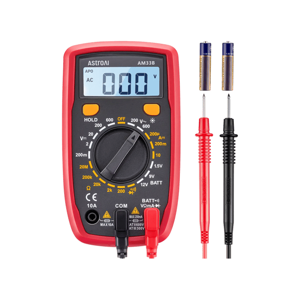
AstroAI AM33B — 2000 Counts
The AM33B is a compact, straightforward meter that covers the core electrical measurements most homeowners and hobbyists ever need: DC/AC voltage, resistance, continuity, and diode testing. Its continuity beep is audible and responsive. The 2000-count display reads resistance in 1Ω increments, which is sufficient for fuse and wiring checks. Not True-RMS — best for conventional home circuits and simple automotive checks.
Best for:
- Checking fuses, switches, and extension cords at home
- Basic car fuse and wiring checks
- First multimeter for a beginner
Not ideal for:
- Modern vehicles with smart alternators (no True-RMS)
- Fine resistance measurements below 1Ω
Best for Home + Automotive Diagnostics
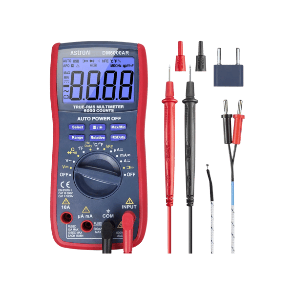
AstroAI DM6000AR — 6000 Counts, True-RMS
The DM6000AR handles every continuity test in this guide and then covers the diagnostics that typically follow: battery voltage, alternator output, outlet voltage, resistance, temperature, and frequency. Its 6000-count True-RMS display and auto-ranging design are useful when you want one meter for both home and automotive troubleshooting. The built-in flashlight is practical for engine bays and electrical panels in low light.
Best for:
- Continuity, voltage, and resistance across home and automotive use
- Drivers who also test battery and alternator health
- Anyone who wants one meter that handles everything
Not ideal for:
- EV/hybrid high-voltage traction battery testing — use a properly rated meter and follow the vehicle manufacturer's safety procedures.
Selection context: For continuity testing, you do not need to buy more meter than the job requires. A basic meter is enough for occasional fuse, switch, and cord checks, while a higher-count True-RMS meter makes sense if you also expect to check household voltage, car battery voltage, alternator output, resistance, temperature, or other diagnostics.
Final Recommendation
The continuity test is the quickest, most definitive way to confirm whether a fuse has blown, a switch has failed, a wire is broken, or an extension cord is safe. The test itself is the same regardless of which meter you use — set to continuity mode, de-energize the component, touch both ends, and listen. What changes between meters is everything else you might want to do after: checking battery voltage, reading alternator output, measuring motor winding resistance. If continuity is all you need occasionally, the AM33B handles it cleanly. If you want a meter that covers continuity and then every other automotive and home electrical test without switching tools, the DM6000AR is the stronger investment.
Frequently Asked Questions
What does the continuity symbol look like on a multimeter?
The continuity symbol looks like a small sound wave or a series of arcs pointing to the right: ))). On many meters, continuity shares a dial position with the diode test — it is often labeled with both the arc symbol and a diode triangle. If your meter has a button to switch modes at that dial position, press it until you hear a test beep when the probes touch. Older meters without a dedicated continuity mode use the lowest Ω resistance range instead.
Does the multimeter need to be on a specific range to test continuity?
No — the continuity mode on a digital multimeter is fixed-range and does not require you to select a resistance value. Simply turn to the continuity position and start testing. If you are using the Ω resistance mode instead (for meters without a dedicated continuity setting), select the lowest available range — typically 200Ω. Most components that should show continuity have well under 30Ω of resistance when intact.
Why does my multimeter beep even when I'm not touching anything?
This usually means the probes are touching each other, or there is a conductive path between the probe tips through something on your workbench (foil, damp surface, bare wire). Some meters also have very sensitive continuity thresholds — they trigger at higher resistance values. Check your meter's spec sheet for the beep threshold (commonly ≤30Ω, but some meters beep up to 100Ω or even higher). If the meter beeps on air, the leads may be damaged or shorted internally.
Can I test continuity on a component that is still installed in a circuit?
You can only if the component is completely isolated from any parallel path. In practice, this rarely applies — most installed components are part of a circuit where other resistive paths exist. Those parallel paths create false continuity readings, leading you to conclude a blown fuse or open switch is fine when it is not. Always remove the component from the circuit before testing. For wall switches, disconnect the wires from the terminals. For car fuses, pull the fuse free.
What is the difference between a continuity test and a resistance test?
A continuity test is a simplified resistance test with an audible alert. The meter sends a small current through the component; if resistance is below the threshold (typically ≤30Ω), it beeps. A resistance test (Ω mode) measures the actual resistance value. For most pass/fail checks — good fuse vs. blown fuse, intact wire vs. broken wire — the binary continuity beep is faster and more convenient. When you need to know the actual resistance value (checking a motor winding, measuring a sensor's output impedance), use Ω mode and read the number.
Can I test continuity on a 240V circuit or a car's 12V system?
Yes — but only after turning off the power completely and isolating the part you want to test. For a 240V circuit: turn off the double-pole breaker and verify with a voltage tester before disconnecting any wires. For a car's 12V system, switch the ignition off and remove the fuse or disconnect the component before testing. If you are working near exposed wiring, the fuse box, or an unknown circuit, disconnect the negative battery terminal first.
What does OL mean during a continuity test?
OL means “open loop” or “over limit.” In continuity testing, it usually means the meter does not detect a complete conductive path between the probes. For a fuse, wire, or closed switch, OL usually indicates a break or failure. For an open switch, OL is the expected result.
Is continuity the same as zero ohms?
Not exactly. Continuity means the resistance is low enough for the meter to consider the path complete. A short wire or good fuse may read close to 0 Ω, but longer wires, coils, or components may have measurable resistance and still show continuity. Always compare the reading with the expected resistance for that component.
Why does my multimeter show resistance but no beep?
Many meters only beep below a certain resistance threshold, such as 30 Ω, 50 Ω, or 100 Ω depending on the model. If the component has higher resistance, the meter may show an ohm value but stay silent. In that case, use resistance mode and compare the number with the component's expected specification.
Can continuity mode damage a multimeter?
Continuity mode itself is safe when used on de-energized components. The risk comes from applying external voltage while the meter is in continuity mode. Live voltage can damage the meter, blow its internal fuse, or create a shock hazard. Always turn off and verify power before testing continuity.
Do I need to remove a fuse before testing continuity?
Yes, removing the fuse is the most reliable method. Testing a fuse while it is still installed can create false readings through parallel circuit paths. Pull the fuse free, touch one probe to each terminal, and replace it only with a fuse of the same amperage rating if it has blown.
What resistance value counts as continuity?
There is no universal value because each multimeter has its own continuity beep threshold. Many meters beep below about 30 Ω, but some trigger at higher values. For a fuse or short wire, near 0 Ω is expected. For coils, heating elements, sensors, or long cables, compare the reading with the component's specification.
Why does my multimeter show OL instead of 0.00?
OL means the meter is not detecting a complete conductive path between the probes. A 0.00 Ω or near-zero reading means very low resistance. In continuity testing, OL usually means an open circuit, while 0.00 Ω or a beep usually means continuity.